
Learning about Time Multiplexing
Lab Report
Introduction
This lab, we extend our single digit seven segment display into two digits. To do this within the constraints of our FPGA, we implement time-multiplexing, alternating between the displays.
Design and Testing Methodology
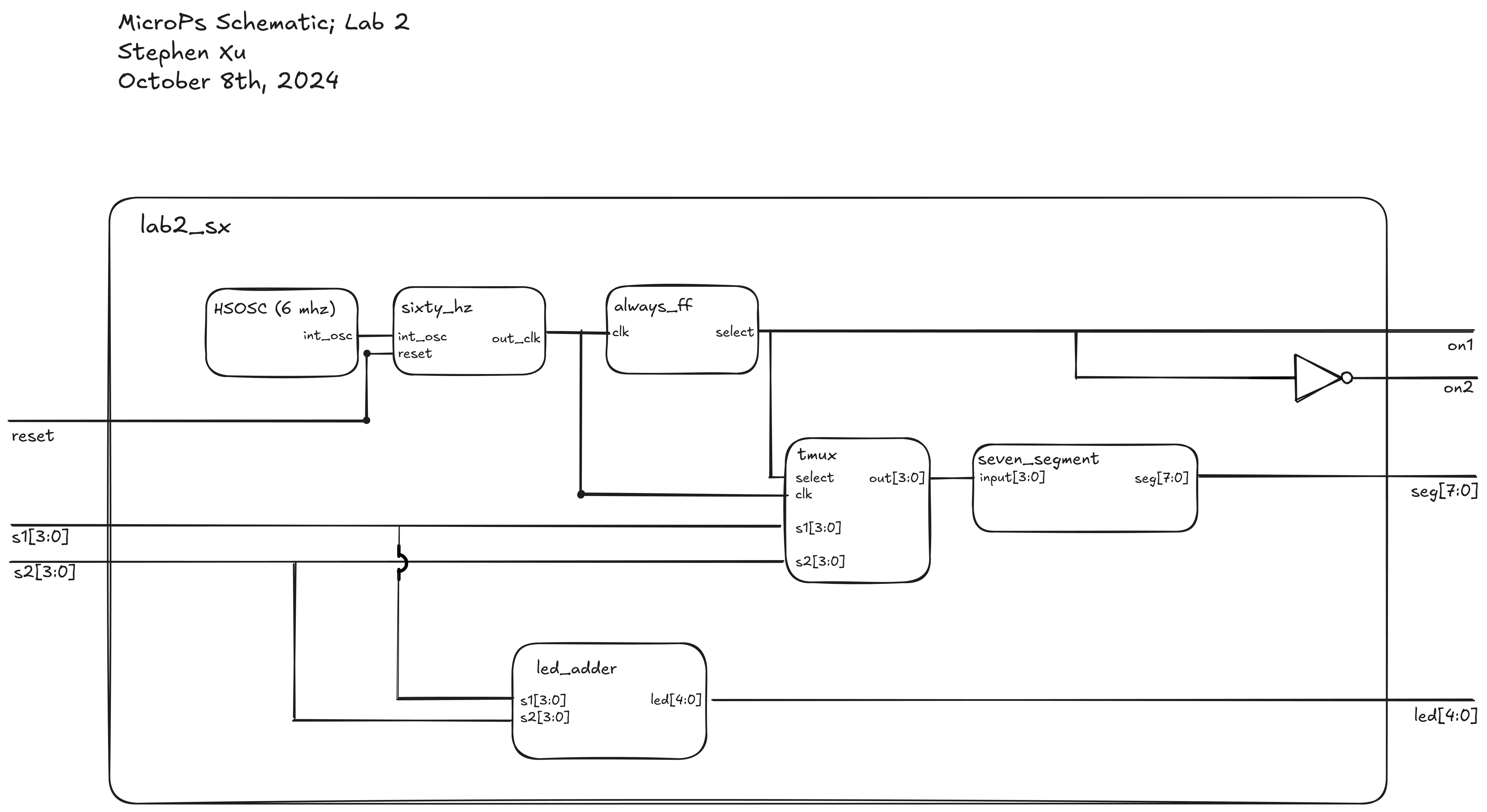
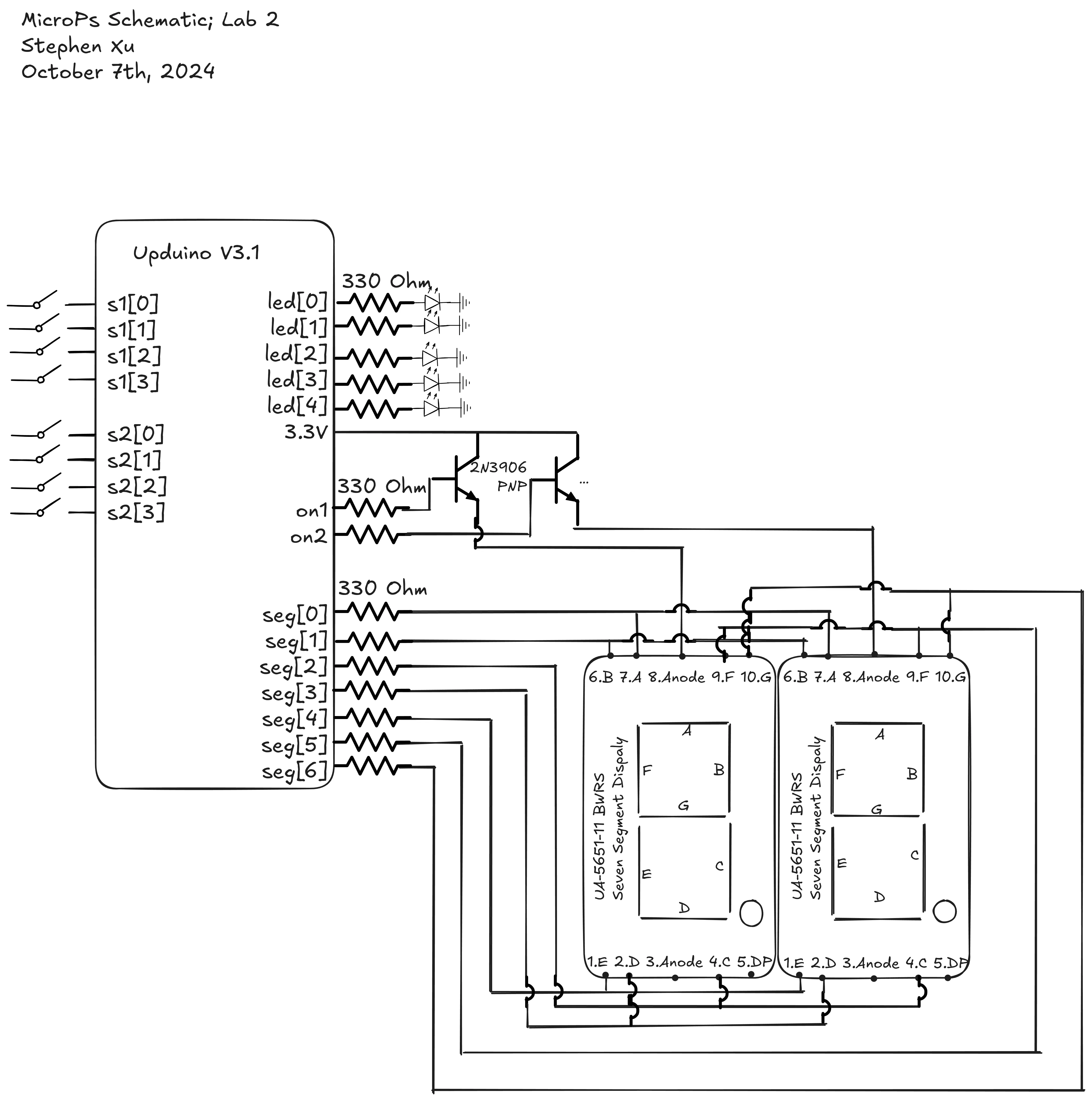
We still only have the same amount of pins for output to the seven segment display, so we implement time-multiplexing. We can’t simply alternate our FPGA pins, as the current from the FPGA is not enough to drive the LEDs. So instead, we use a set of two PNP transistor to toggle signal from 3.3V at 240 Hz, which gives the appearance of having two solid displays. In addition, we display the sum of our two inputs on a set of five LEDs.
Technical Documentation
The source code can be found in this repository.
Block Diagram
Schematic
Results and Discussion
I’m a bit impressed with myself honestly, I managed to get everything working, which I’m super proud of.
While technically working and all up to spec, there are however a couple minor inconveniences. The first one was because I was working on a really small breadboard, I was unable to manage to fit the second DIP switch in a convenient location. The other minor inconvenience was a product of a poor job done on the last lab, where I soldered the DIP switch on in the opposite orientation. The two dip switches are also rather oddly placed, with the right DIP switch controlling the left display, and the left DIP switch controlling the left display. It’s worth mentioning that all these problems are fortunately also fixable in SystemVerilog.
Testbench Simulation
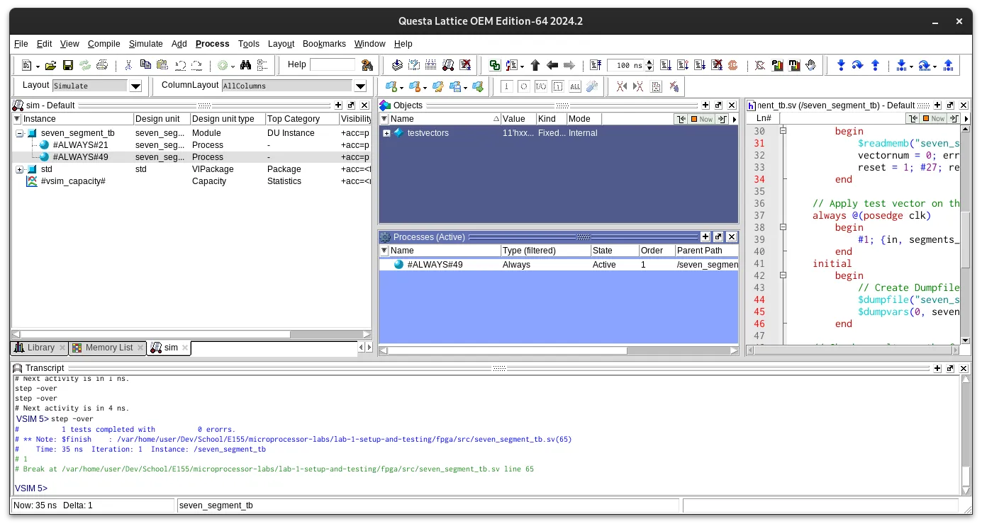
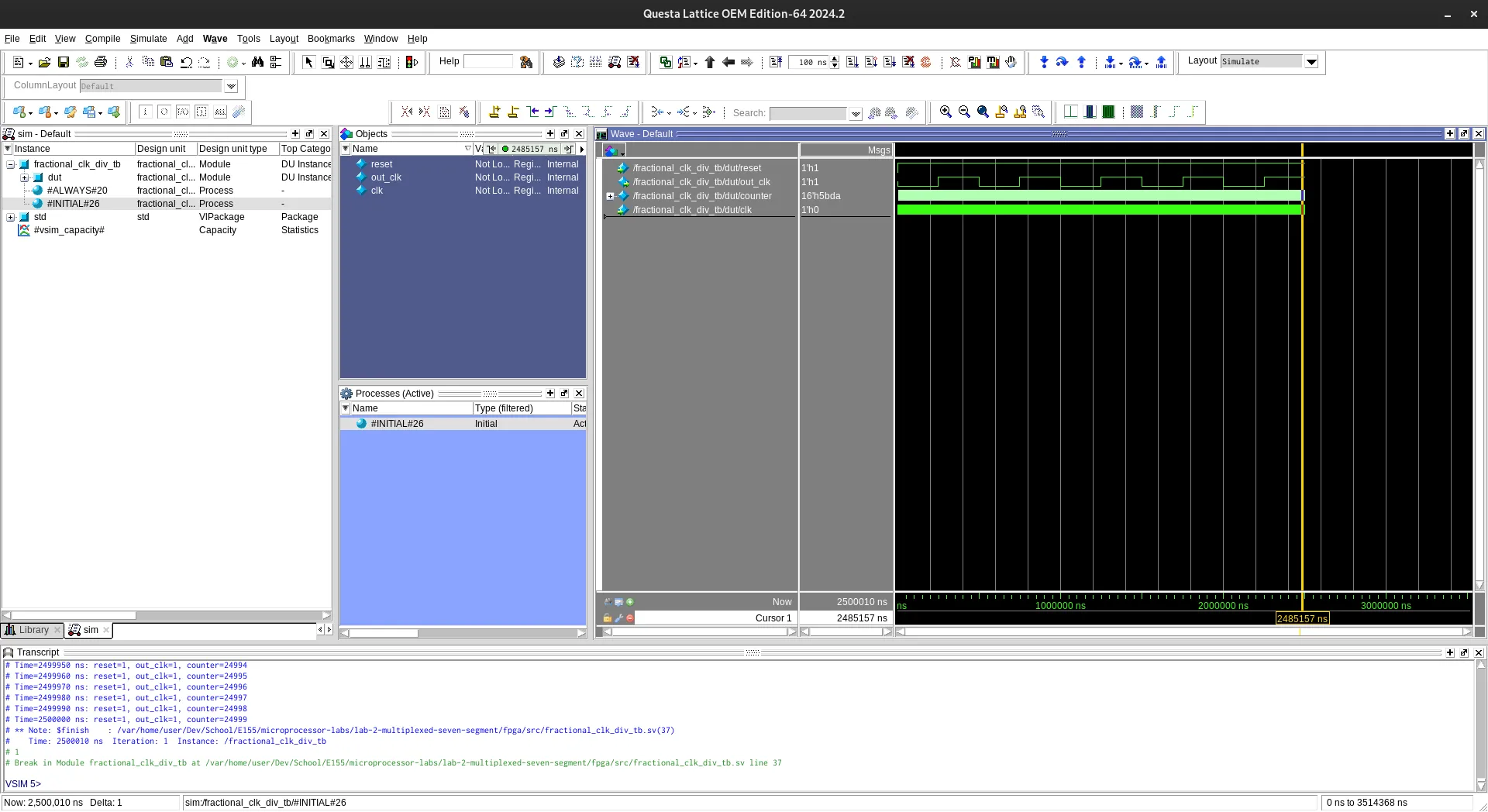
The seven segment module was already tested in the previous lab. For this lab, I’ve tested the time_multiplexer module, as well as the new fractional_clk_div module.
Here’s the seven segment module:
Here’s the testbench output for the fractional_clk_div module.
The time_multiplexer has also been tested here.

Current Draw Calculations
The specsheet for our current draw for the Lattice iCE40 UP5K FPGA can be seen here:
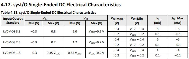
As you can see, the maximum current draw from an output pin is 8 mA. Because we have V = 3.3V, then we can calculate the resistance needed for our maximum output current as R = 3.3V/8 mA = 412.5 ohms. I am unfortunately however using 330 ohms, so I do fall outside the spec for the current draw, obtaining a 10 mA current. Oops.
Conclusion
This lab took me a lot less time than the previous lab to finish, amounting to ~14 hours to complete. I feel like I took longer than my classmates, but overall this is a significant improvement in being more efficient with my work, which has made my pretty happy.
I think for future weeks, I’ll work on writing the test benches earlier, as well as just doing more work before diving and just wiring in electronics. However, I’m not sure if this will actually save me all that much time. At least for me, it seems that I don’t understand the lab very well at the beginning, and find just wiring things and passively thinking about the logic in the meantime as pretty valuable.
Notes
Transistors
In this lab, I’ll be using transistors to switch the current between the two seven segment displays. While learning about transistors, and figuring out how to wire them, this youtube video was very useful.
Reflection
This week’s lab went a lot better! So far this class has been an incredibly eye opening experience into how digital electronics work. This lab for example, made me realize how much is abstracted away in order to just display two numbers. It makes me think a lot more about what I might be missing out on, things that I don’t really understand as well as I could.
As an example, before this lab, I would have thought that the segmented display on your standard basic calculator would be quite uninteresting. But I’ve since realized how many different design decisions could have gone into just making that calculator display the numbers you’re putting onto the keypad (coincidentally, the next week’s lab involves implementing a keypad). Especially cool to me was the idea of multiplexing this week, that we could switch between the displays, and turn them on at a high enough frequency, and our eyes wouldn’t be able to tell.
I think I’ve been aware that I’m not too curious of a person. I’m often willing to accept explanations for things, without much further consideration. I have been recently trying to change this. I’m not sure if it’s this class or just me actively trying to be more curious, but it’s been cool to observe my mind wandering a lil :)