
Microprocessor (Mis)adventures - Wiring up a seven segment display 😵💫
Disclaimer ‼️
This semester, I decided to sign up for E155, which is my college’s microprocessors class. This post is going to be about the first lab, which pretty much involves setting up the FPGA dev board, and a bit of SystemVerilog programming. This assignment was really fun! It might just be the most fun I’ve had doing homework as long as I can remember. Unfortunately, I also have no idea what I’m doing.
For a little more context, this was a screenshot of a portion of the class’s pre-course survey.
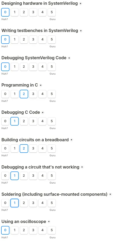
As you may be able to see, I am a little bit lost. For some reason a friend encouraged me to take this class, and the most relevant thing I’ve ever done has been to assemble redstone circuits in Minecraft.
Lab Report
This lab took me a total of 23 hours!!, mostly because my lack of knowledge (as mentioned above).
In this first lab, we were given a PCB board, FPGA and microcontroller (MCU). The first part of our lab involved soldering on a bunch of components so that we could actually connect the FPGA and MCU, setting up our “Development board”, intended to be used for the rest of the semester. The second part of the lab involved designing a circuit to display hex digits on a seven segment display based on several switches, and then coding it up in SystemVerilog.
More formally, we had the following requirements:
- Take four DIP switches
s[3:0]as input - Wire up a seven segment display
- Do it in a way such that each segment of the display is equally bright no matter the amount of segments powered
- Write SystemVerilog code to control it based on the output of the four DIP switches
- Calculate current draw to ensure that it meets operating conditions based on provided spec
- Also control three onboard LEDs
- Two LEDs output based on combinational logic of the switches
- The third one runs on a 2.4 Hz clock and flashes on and off
- Write testbench code for all of the above :D
I did the above, with one caveat. THe LED runs at 2.44 Hz, due to questionable* design. If I wanted it to run at exactly 2.4 Hz, I would have to redesign my LED to either pulse using a strobe signal, or utilize a fractional clock divider.
In addition, here is the github containing the code for this lab, as well as all the other labs I (might) do in the future.
Assembling the board
This part took me ~14 hours. I definitely could’ve done it in less time, which I’ll touch on more later.
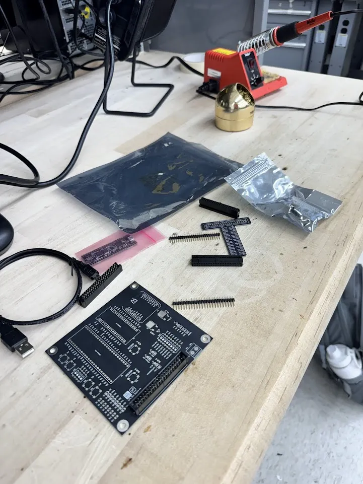
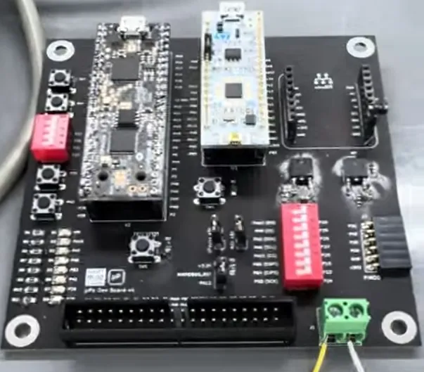
Here’s a (badly taken, sorry!) picture of the lab kit I was given.
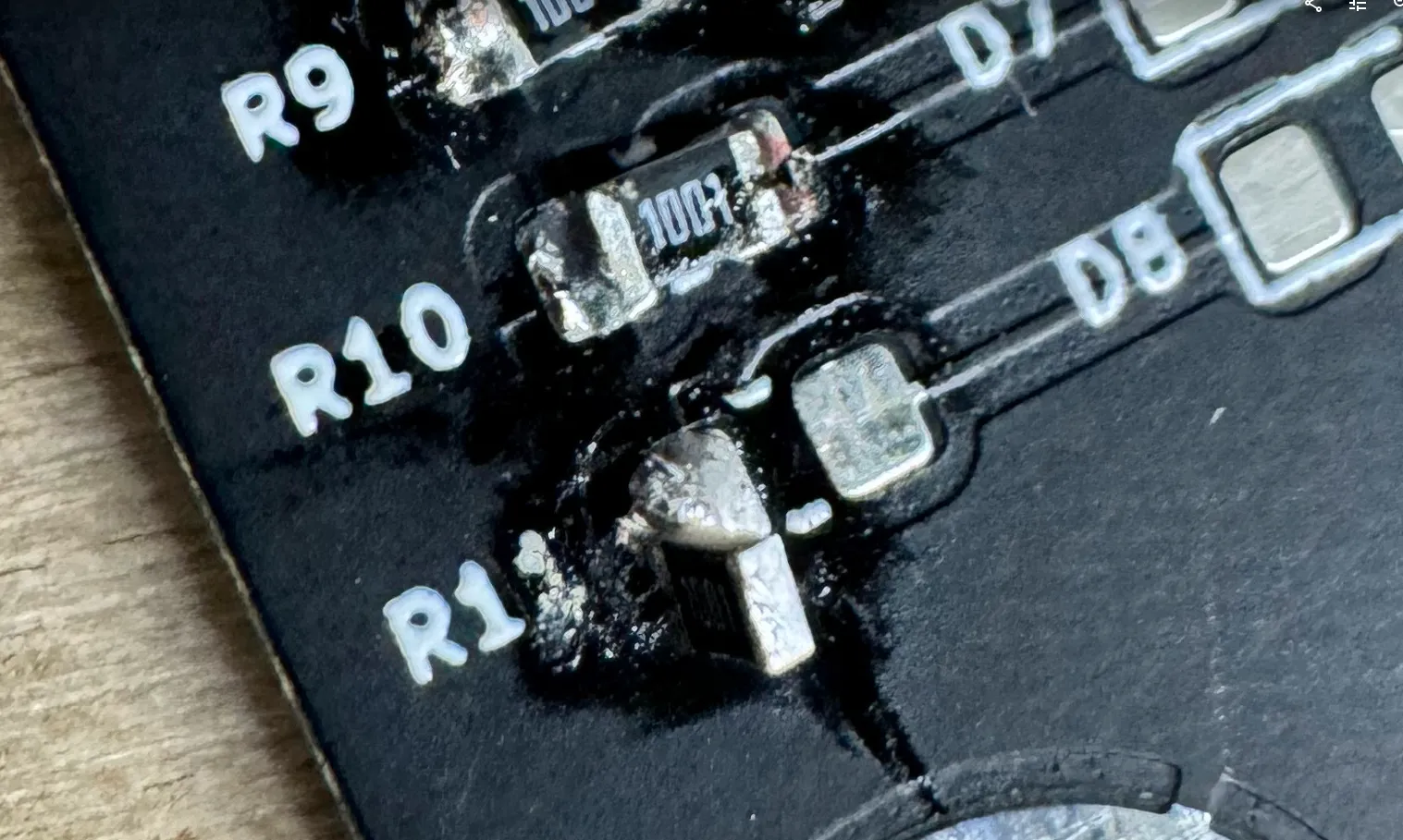
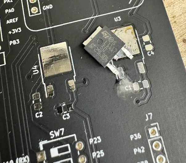
Here’s a couple pictures of soldering mishaps.
And here’s the final product after soldering :D
This process took me a really long time. Spending this much time was definitely avoidable too! I rushed through a lot of the soldering really quickly, as well as reading the instructions, which ended up costing me several hours compared to the couple minutes I saved. Really bad move, especially considering my inexperience with soldering, doubly so with such tiny SMT components. Lesson learned for next time. 👍
In addition, I also spent a lot of time testing and debugging issues that I ran into. The first of those was that the voltage regulator didn’t seem to work,so I had to reflow the solder several times. When I went to upload test code, there were also a bunch of pins which weren’t soldered properly, so I had to reflow those as well.
The other issue was that I broke a small part of my 2x20 female connecter while trying to crimp my ribbon cable. I spent about two hours freaking out and trying to find a replacement. Ended up just rolling with it, and it worked fine, so it really actually matter in the long run. I eventually mustered up enough courage to ask my TA about it, and he said that he did also broke it too, and just superglued it together. During that time I spent a lot of time stressing and considering just dropping the class then and there, so there was a lot of wasted stress and time over such a minor issue.
The Light!
The next morning after that was the labor day holiday, so there was a bit of extra time for me to finish this lab.
I did end up wasting some time here as well, messing around with the seven segment display. I didn’t think to look up documentation, so I was just plugging in random pins trying to get the seven segment display to light up. This took me around an hour to figure out how it worked. I however, don’t really regret this, because it was actually kind of fun to just plug in random things and see how the circuit behaved. It was also only an hour, so the time wasted wasn’t too great, and also gave me some time to think a bit about how to design the rest of the hardware.
If you want a TLDR on the design, just skip to the diagrams.
SystemVerilog
This was my first time writing SystemVerilog code. Once I got past a bit of the initial confusion, it didn’t seem that bad, at least for this project. Having a decent amount of programming experience helped for sure, although I’ve been told not to think about SystemVerilog as a programming language, and instead as a way to describe your hardware design.
In terms of functionality, there were pretty much three things I actually had to implement. The seven segment display, combinational logic for two LEDs, and also a 2.4 hz clock for the third LED.
It seemed logical to start with easy stuff, like the combinational logic for the LEDs. To do so, I wrote the following SystemVerilog code.
module lab1_sx(
    // 48 MHz clock on FPGA
    input logic clk,
    // the four DIP switches (on the board, SW6)
    input logic [3:0] s,
    // 3 LEDs (you may use the on-board LEDs)
    output logic [2:0] led,
    // the segments of a common-anode 7-segment display
    output logic [6:0] seg,
);

    // led[0] can be modeled as XOR of S1 and S0 switches
    assign led[0] = s[1] ^ s[0];

    // led[1] can be modeled as AND of S2 and S3 switches
    assign led[1] = s[3] & s[2];

    // TODO: led[2] blinks at every 2.4 hz.

    // TODO: seven segment decoder here

endmodule
Unfortunately, this code didn’t synthesize. Can you spot why? Well, I couldn’t, at least for about two hours. At the time, I didn’t realize that Verilog threw error and warning messages at the time, so I sort of just stared at the code. I wouldn’t find out until much later, that in fact, it does.
I’m honestly unsure why I thought it wouldn’t have error messages. It didn’t throw the error message at me, and me knowing that I had no idea what I was doing, sort of just thought that because it was hardware, it worked differently.
Anyways, enough rambling. Turns out that after two hours, I finally got the idea that maybe, Verilog was sort of like json, and removed the extra comma in the input variables.
-    output logic [6:0] seg,
+    output logic [6:0] seg
And then it worked! I was so happy after this. I’d finally written working SystemVerilog code!
Writing the seven segment display code was actually rather straightforward. I split it into a different module called seven_segment. It’s essentially just a giant truth table, enabling pins. Fairly simple. There were a couple syntax issues that I had to painfully stare at the screen and debug, as well as trying to get the digits to line up properly.
module seven_segment(
    // input to seven segment display
    input logic [3:0] in,
    // pins for segment output
    output logic [6:0] segments
);

    // For model UA5651-11EWR5 of 7-segment displays
    // May work for others as well
    // Currently does not support decimal points
    // abcdefg is referring to the following layout
    // https://commons.wikimedia.org/wiki/File:7-segment_labeled.svg
    // 0 is on, 1 is off

    always_comb
        case(in)                   // abcdefg
            4'h0:       segments = 7'b0000001;
            4'h1:       segments = 7'b1001111;
            4'h2:       segments = 7'b0010010;
            4'h3:       segments = 7'b0000110;
            4'h4:       segments = 7'b1001100;
            4'h5:       segments = 7'b0100100;
            4'h6:       segments = 7'b0100000;
            4'h7:       segments = 7'b0001111;
            4'h8:       segments = 7'b0000000;
            4'h9:       segments = 7'b0001100;
            4'ha:       segments = 7'b0001000;
            4'hb:       segments = 7'b1100000;
            4'hc:       segments = 7'b0110001;
            4'hd:       segments = 7'b1000010;
            4'he:       segments = 7'b0110000;
            4'hf:       segments = 7'b0111000;
            default:    segments = 7'b1111111;
        endcase
endmodule
The 2.4 Hz clock to turn on the third LED ended up being a lot more complicated. I think there are better ways to do it, like a fractional divider or a strobe signal, but the example I found on the internet didn’t make much sense to my tired brain at the time. Instead, I adapted my Professor’s example of an imperfect 1Hz clock to create an imperfect 2.44 Hz clock. I think I have a much better idea how to actually implement a 2.4 Hz clock now however.
However, if you would like to have an idea of how this clock divider works, it essentially uses the LSOSC (Low Speed Oscillator) clock running on the FPGA, which runs at 10k Hz, and creates a 12 bit counter. Then we have 10000/2^12 = 2.441. There are several other flaws with this code, including the fact that there’s no reset coded in.
Here’s the final code with the included clock divider:
module lab1_sx(
    // reset
    input logic reset,
    // the four DIP switches (on the board, SW6)
    input logic [3:0] s,
    // 3 LEDs (you may use the on-board LEDs)
    output logic [2:0] led,
    // the segments of a common-anode 7-segment display
    output logic [6:0] seg
);

    // led[0] can be modeled as XOR of S1 and S0 switches
    assign led[0] = s[1] ^ s[0];

    // led[1] can be modeled as AND of S2 and S3 switches
    assign led[1] = s[3] & s[2];

    // led[2] blinks at every 2.4(4) hz.

    logic int_osc;
    logic [11:0] counter;

    // Internal low-speed oscillator
    LSOSC OSCInst1 (
        // Enable low speed clock output
        .CLKLFEN(1'b1),
        // Power up the oscillator
        .CLKLFPU(1'b1),
        // Oscillator Clock Output
        .CLKLF(int_osc)
    );

    // Counter
    always_ff @(posedge int_osc) begin
        if (reset == 0) counter <= 0;
        else            counter <= 12'(counter + 1);
    end

    // seven segment decoder here
	seven_segment display (
        s,
        seg
	);

    assign led[2] = counter[11];

endmodule
As an added bonus (and because the assignment requires it), here are some quick calculations to demonstrate that the current draw for the seven segment display is within it’s recommended operating conditions.
The part number for this is the UA5651-11 EWRS seven segment display. The specsheet I found online, says that the maximum current draw per LED at room temperature is going to be 30 mA. I’m passing 3.3V through, and each LED is run through in parallel with a 220 ohm resistor. Using V = IR, we find that assuming the LEDs and other components add negligible resistance, we have an upper limit on our current draw at I = V/R = 3.3/220 = 15 mA, which is about half our maximum current draw. So we’re doing fine!
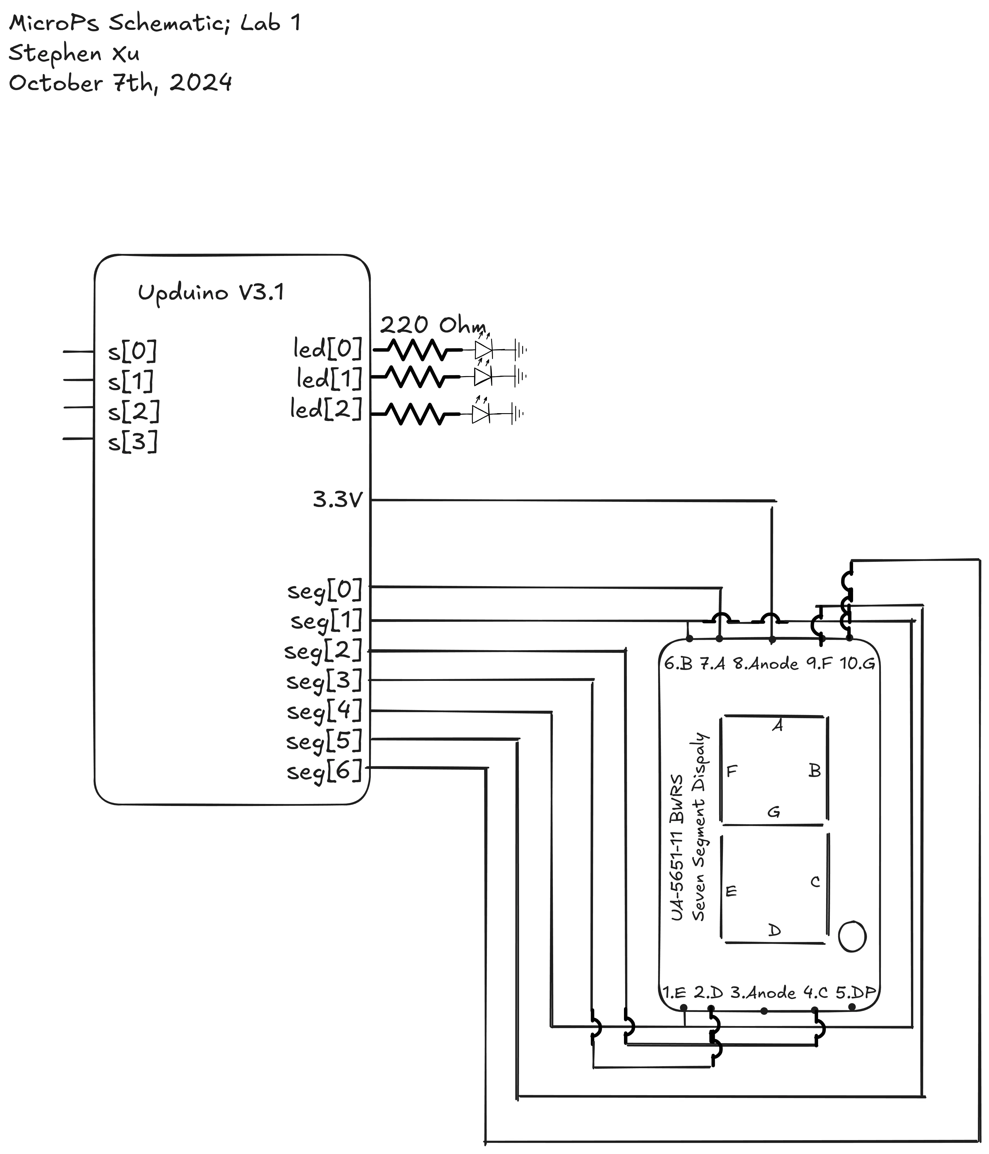
Diagrams
To help explain the (fairly simple) design a bit better, here’s a schematic (left) and a block diagram (right) of what’s happening.
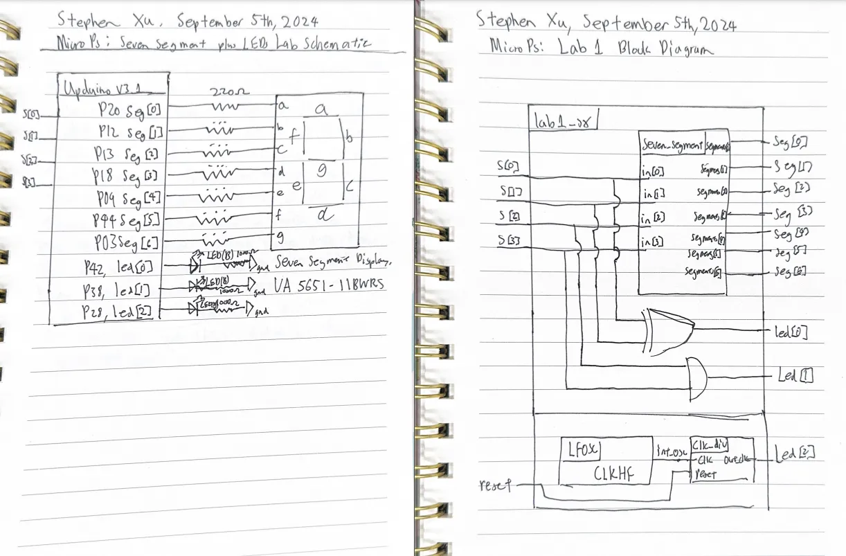
Edit: 10/7. I updated the schematic with one drawn with excalidraw, with pin numbers on the 7-segment display properly labeled.
Testing Code
I procrastinated on writing the testbenches for a long time. Fortunately, it was actually very easy to get working, this part took me ~ 1 hour.
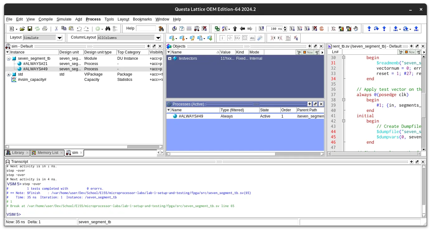
Here’s the transcript output:
#          1 tests completed with          0 erorrs.
# ** Note: $finish    : /microprocessor-labs/lab-1-setup-and-testing/fpga/src/seven_segment_tb.sv(65)
#    Time: 35 ns  Iteration: 1  Instance: /seven_segment_tb
More thoughts and reflections
The add deadline for my college is on 9/9, which is four days after the publication of this article. In other words, I have four days to decide whether or not I want to drop this class and replace it with another. I suppose this blog post is a good opportunity to reflect on whether or not I want to do that.
I think I first have to consider my motivations for this class, and what I want to get out of it. To be honest, I decided to sign up for this class on a whim, the night before my registration time. I saw it perfectly fit with my planned schedule, and could give me elective credit if I decided to pursue a joint major in computer science and mathematics, so those decidedly helped convince me.
But I think what appealed to me most was how at the time, I felt like school was a bit boring. In particular, I was enrolled in a course on Abstract Algebra. While I LOVED the class (and math in general, I actually want to take more algebra courses in the future), at times it felt like I was just moving imaginary things around. It was missing a connection to the real world. As an example (and a side tangent), I remember discussing about how the integers are not exactly a subset of the rational numbers, which while I understood, also felt disconnected and crazy.
Microprocessors instead, felt like it offered me a way to play around with something I very much love - digital systems, in a very physical and tangible way. It also felt like a good opportunity to dive headfirst into learning about computing on a much lower level of abstraction than I was used to thinking at. I don’t want to call myself a masochist, but some of my friends do insist that I am, so it’s also true that part of me was looking for a challenge.
I do however feel like I like the challenge not because I like to suffer. Rather, I think that one of the things I like to do most is learning, and I tend to associate challenges and struggling with things with the periods of things in my life where I’ve had the most productive and explosive moments of growth. As an example from my own personal experiences, in freshman year of high school over the pandemic, I was invited to join a startup. Immediately after I joined, it exploded in size. I didn’t really know how to code before, and was completely lost rapidly trying to add things to accommodate our growing userbase, but by the end of a summer I think I learned a lot more than what motivation alone could account for.
As I currently tutor a couple high school students, I think about learning sometimes. Some of the students I tutor are both incredibly talented and motivated, quite definitely more so than I was at that age. But they seem to learn at a much slower pace. I wonder if it’s because the curriculum I give them is carefully designed, something that moves them along step by step and provides them with everything they need to know. None of them have had the experience of having to frantically google and debug code at 3 am in the morning when hundreds of servers suddenly go down and you barely know how to program. Intuitively, this “trial by fire” method of learning feels like an incredibly bad way to learn things, and I wouldn’t dream of making one of my tutees go through this.
But the reason I bring it up, is that taking this class and doing this first lab has reminded me of that period of my life. These first couple of lectures, it’s felt like almost every other word or concept the professor mentions is completely new. Truth be told though, I’m in a period of time where I’m currently also frustrated with my own learning. It feels like I’ve stagnated since then. In the time between freshman year of high school, and to my life now, as a sophomore in college, I don’t really think I’ve learned much. While I definitely have grown as a person, especially in my ability to write, it feels like from a technical ability standpoint, I’ve stood nearly still. I feel this particularly hard when I reference code I’ve written years ago, when I’m stuck and suddenly remember that I’ve solved a specific problem before.
But yet, at the current level of work I’m putting in, is likely to be unsustainable. I did eventually quit the startup I mentioned earlier because although I found it incredibly fun and fulfilling, I eventually got burnt out and drifted towards other hobbies. Putting 20+ hours towards this class’s lab is something I know I won’t be able to do week after week for the rest of this semester, at least without harming my health. I was only able to do that for this first lab, because it fell on a week with a long weekend. However, over the course of this writeup and reflection, I have noticed that there were definitely several areas of improvement, that could’ve saved many hours. It’s possible that over future weeks, I’ll be able to learn more and more, and complete the labs in more timely manner. What I’m worried about is that the labs get harder and harder, so that instead of the time to complete getting shorter, they actually get longer.
Another thing that I would be lying if I said I wasn’t worried about are my grades. My parents for one, think that taking any class that could ruin my pristine GPA is a horrible idea. They’ve been telling me to drop this class as soon as they found out I was taking it. Fortunately, I don’t subscribe to this idea, and I’ve never listened to my parents much anyways (oop). I think something I believe, at least in principle, is how much you learn is what’s most important. But other people do however believe in the importance of grades, and it’s something to be cognizant of, at least for future learning opportunities. For example, if I had bad grades before I came to college, I’d likely not be admitted in as great of an institution for learning as I am in now. And as someone who’s uncertain about their future, it’s possible that graduate school may be in the cards.
Furthermore, another question that needs to be asked is why now? If I drop it now when I feel like I might not be able to handle it, I still have two more years to come back and take this, perhaps with an easier schedule, or having learned more, or having taken one of the pre-requisite courses. At the same time though, that feels like running away from a challenge. Perhaps what I’m really scared of is taking a risk. I might just have to flip a coin.
// end rant and half formed thoughts, o7, thanks for reading