
Microcontroller Interrupts!
Introduction
For this lab, I used an MCU to measure the speed a 25GA-370 motor was spinning at. I did this by taking advantage of interrupts, and interfaced with a quadrature encoder built into the motor to calculate the speed of the motor in revolutions per second.
Design and Testing Methodology
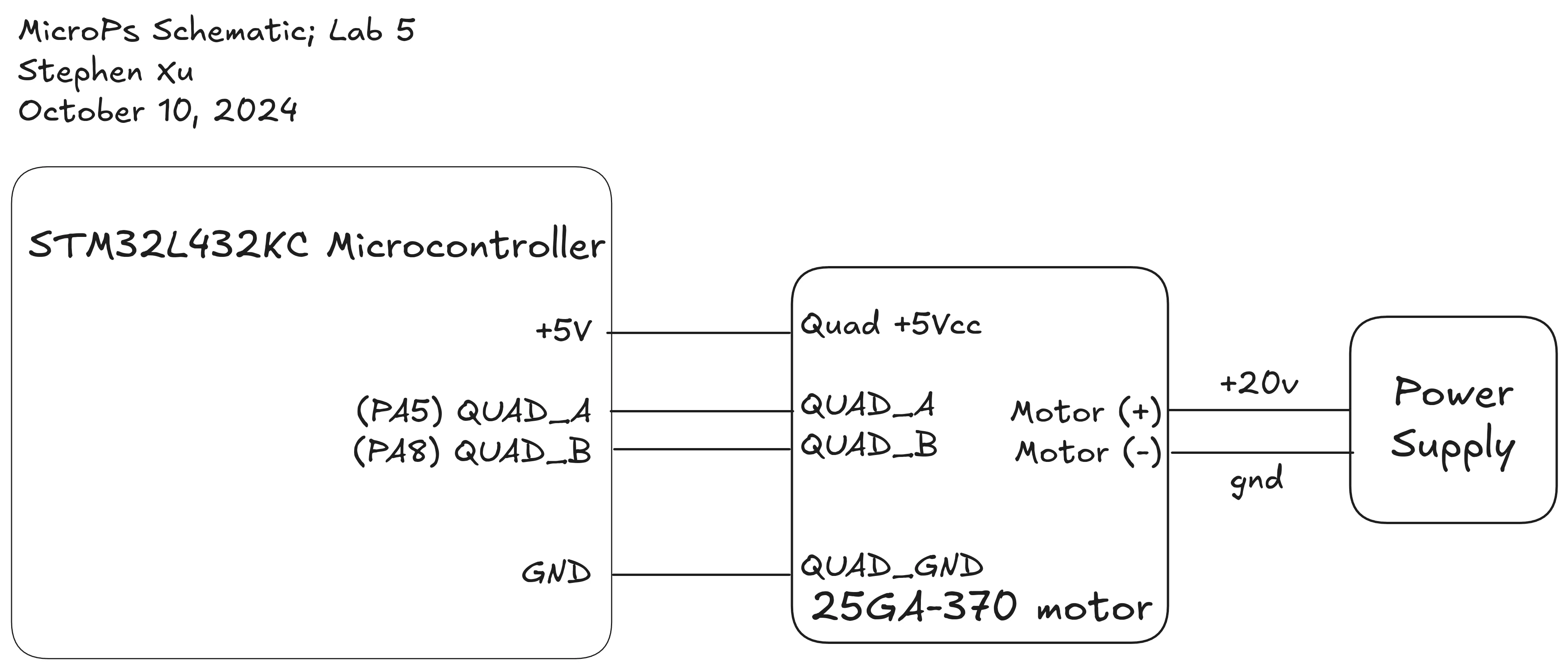
The Quadrature encoder for the 25GA-370 motor is wired as shown below.
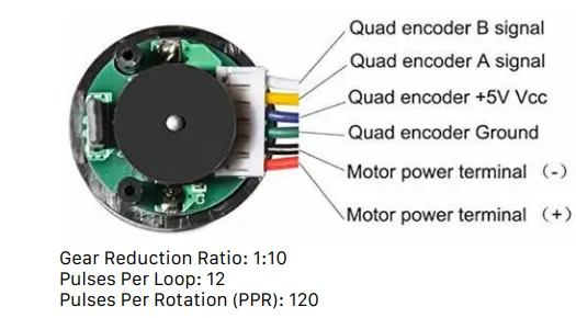
As you can see, there is both an A and B signal output. They are put ninety degrees out of phase. This allows for the ability to measure both the speed of the motor and the direction.
The GIF demonstrating the output signal (taken from my course website) is displayed below.
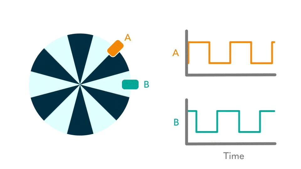
I then essentially take four of these interrupts, two for each signal (once on rising edge, once on falling edge), and use each of those to compute the time difference and compute the speed of the motor.
From the beginning, I planned to test this motor running at 12V, which should give me a 600 rpm -> 10 rev/s output according to the specsheet. I then planned to compare the results of measuring the speed of the motor with only a polling method, which I can measure by making the mcu print the results over UART to my computer.
Calculations
To calculate the speed of the motor, I took advantage of data from the datasheet, indicating that it would have 120 pulses per rotation. So to get the amount of pulses, I used the interrupt code to measure the pulses from the falling edge of A, rising edge of A, falling edge of B, rising edge of B and incremented the amount of pulses each time, while keeping track of the amount of time elasped between those pulses .
I then took a running average, and printed out the speed of the motor every 100 milliseconds, (or 100,000 microseconds). I found this to be a good balance to get as accurate of a measurement as possible, and to get good response times.
To calculate the direction of the motor, I also kept a running count of the amount of times A went high before B (A rising edge while B is low), and compared it to when B went high before A (B rising edge while A is low), and if the first count was higher, then it was traveling counter clockwise, or , and if not, then .
So the formula to calculate the speed ended up being the following
Interrupts vs Polling
I ended up implementing both, just to see the comparison. I did use the oscilloscope to confirm the values, which should be around .
Here is a picture of the oscilloscope trace, which indicates a frequency of 1.19 kHz, and a corresponding speed of .
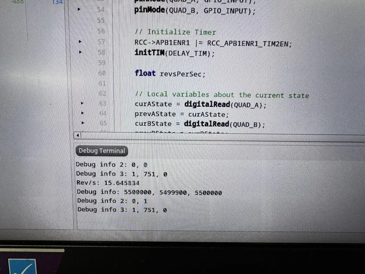
And here is the polling output (15.64 Rev/s):
And here is the interrupts output (9.859 Rev/s):
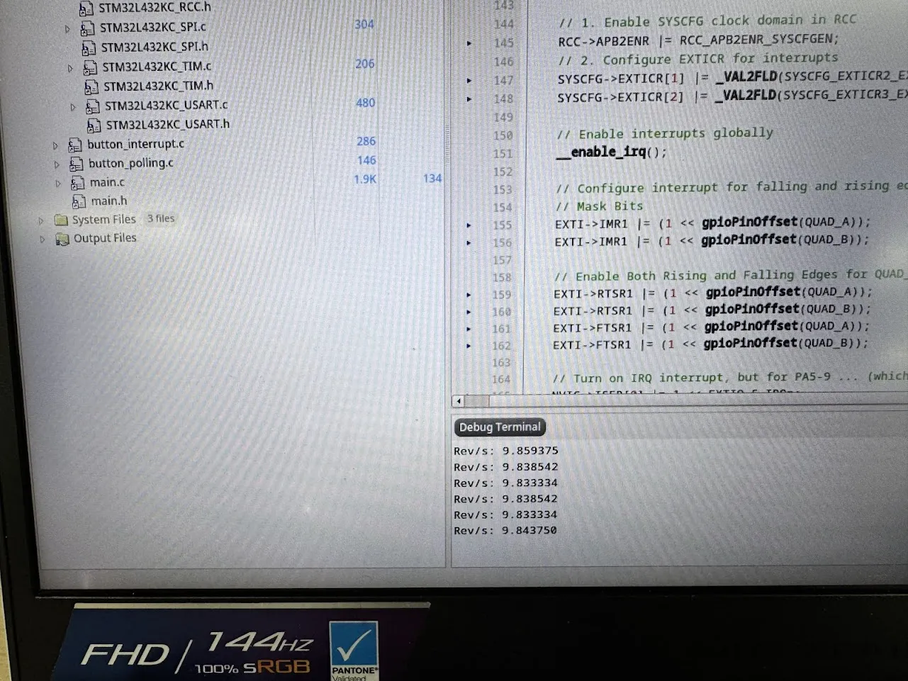
So the percent error for interrupts is ((9.9167-9.859)/9.9167) = 0.05%, while the polling output is something more like 57.7%.
As you can see the percent error for interrupts is considerably lower! But I wasn’t sure if this was the best form of comparison between polling and interrupts, I actually felt like the polling rate was somewhat accurate enough in this case, and I could always make the timer more precise to poll at faster frequencies. I can definitely imagine cases where polling is really important, but it didn’t seem to actually matter this much for this lab, if I wanted a better accuracy, I could’ve configured the timer to delay at a higher rate.
Technical Documentation:
The source code for this project can be found in my Github Repository.
Schematic
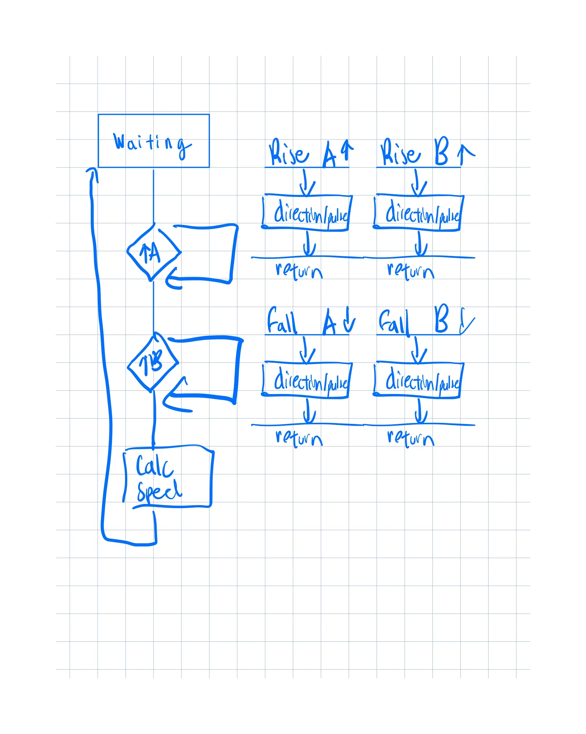
Flowchart
In addition, here is an (admittedly messily drawn) flowchart interrupting the interupt flow of the program.
Conclusion
This project took me 14 hours. I felt like it was an okay amount of time to spend on the project, I did waste a couple hours being pretty stupid, but I think it was okay and expected.