
Music On an MCU
Introduction
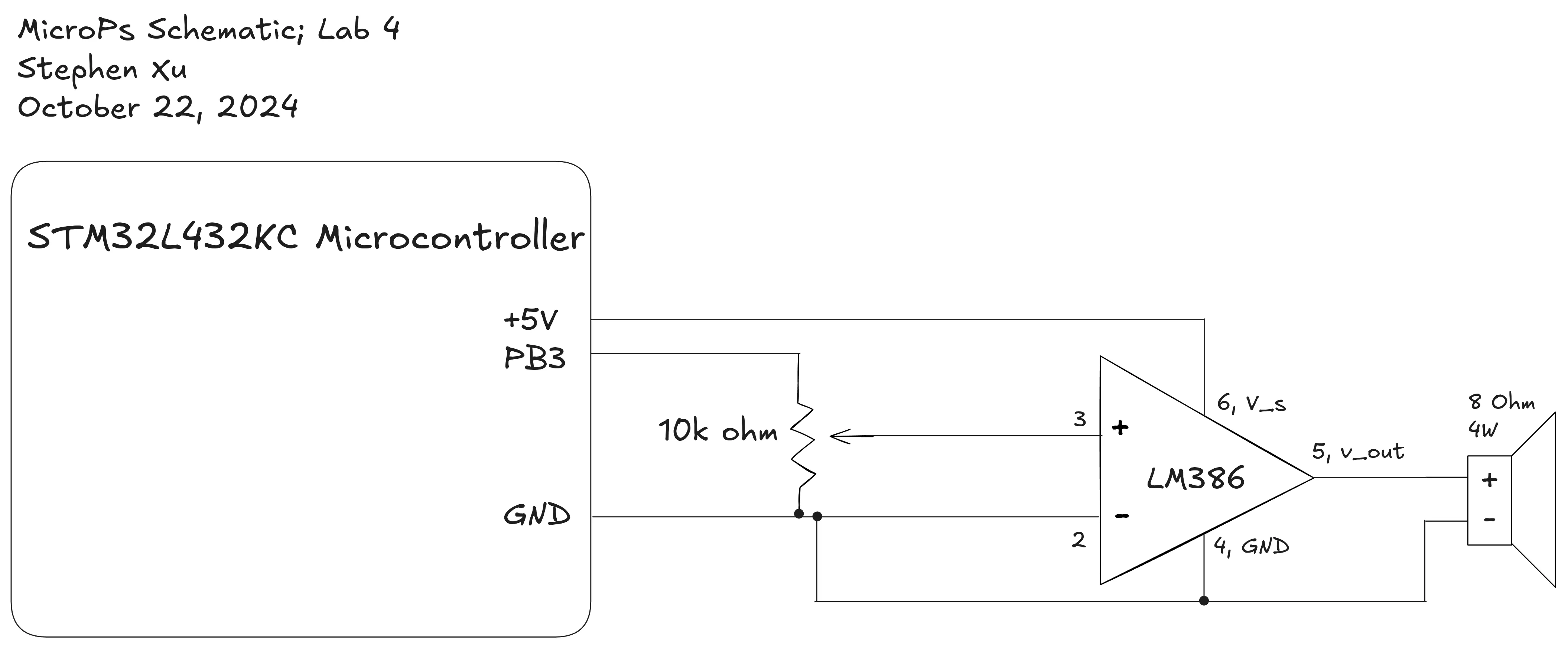
For this lab, I used an MCU to play music. I configured the MCU to generate square waves of various frequencies outputting to an LM386N audio amplifier hooked up to a speaker. Because there is only one speaker, it’s limited on the amount of sound it can play, and is only currently set up to play square waves. There is also some background noise caused by the audio amplifier, which I did not address. I could have addressed it with a noise reduction circuit, but decided not to for the purposes of this lab.
Below is a video of the speaker playiing Fur Elise, and then a custom composistion of my own :). I also demonstrate the potentiometer being able to control audio.
Design and Testing Methodology
This was the first lab using an MCU. We were told to use MMIO directly, instead of using a built in library to talk to our STM32L432KC microcontroller. I used two timers for this lab, one to implement delays, and another set to PWM mode to generate square waves interfacing with the speaker.
To test this, I created a debug LED to indicate when delays were happening, as well as used my ears and my smartphone timer (stopwatch/video) to make sure that the audio being played made sense.
Calculations
To make sure that the frequency ranges I was supplying would actually allow for accurate playback of frequency and delay, I had to do calculations.
To begin with, the system clock was initiated to Mhz.
I set the delay timer prescaler to , so the timer clock was running at .
The minimum delay time I could represent would be
Because the delay timer was a 16 bit timer (and the particulars of my implementation), the maximum delay I could represent could be calculated as
In addition, I set the PWM timer prescaler to , so the PWM timer clock was running at .
This meant that the lowest possible frequency I could generate would be when I divide by the maximum period of 65535.
Meanwhile, the highest possible frequency I could generate is when I divide by the minimum period of 2.
We also need to do error calculation to make sure that all frequencies are within 1% accuracy between 220 hz and 1000 hz. I wrote a short python program to check the error, because I’d also be limited by integer division, and I wasn’t too sure of an elegant way to check for that mathematically.
timer_clock = 80*10**6/(60)

worst_error = 0

for freq in range(220, 1000):
    exact_period = timer_clock // freq
    actual_freq = timer_clock / exact_period
    error = abs(actual_freq - freq) / freq

    if error > worst_error:
        worst_error = error

print(f"Maximum error: {worst_error * 100}%")
This gives us that the highest error within the range is , which is well within our boundary.
Technical Documentation:
The source code for this project can be found in my Github Repository.
Schematic
Listed here is the schematic for the digital audio setup.
Conclusion
This lab ended up taking me a lot more time than I expected, around 20 hours. Not a lot of it was productive, and a lot of it was simply because I wouldn’t spend enough time in one sitting. I’d sort of just look at it for about twenty minutes, get a bit confused, and work on the problem later. I do wish I had spent more time in two hour or so stints, that would have been much more productive. I think those longer periods of time are a lot better for beign able to focus and make progress on the problems that I had to encounter.